


Product outline
Introduction
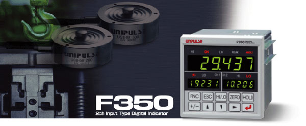
F350 is a digital indicator that is capable of two-channel inputs of strain gauge type sensors. Equipped with calculation functions, such as ch1+ch2, ch1-ch2, F350 is ideal for total, difference, balance and other load measurements.
2 ch inputs
Calculation and judgment outputs can be made for 2 ch input values of strain gauge type sensors. Calculated value is displayed on the main display, and ch1 and ch2 input values are displayed on the sub display.
Calculation functions
● ch1 + ch2: The ch1 value and ch2 value are added.
● ch1 – ch2: The ch2 value is subtracted from the ch1 value.
● |ch1 – ch2|: The absolute value of the difference between the ch1 value and ch2 value is calculated.
● High select: The ch1 value or ch2 value, whichever is larger, is selected.
● Low select: The ch1 value or ch2 value, whichever is smaller, is selected.
9 points of judgment outputs are equipped
● Calculation value: HI, OK, LO
● ch1 value: HI, LO, Alarm output
● ch2 value: HI, LO, Alarm output
Sampling speed as high as 3000 times/sec. on each channel
Including the high-speed CPU that allows processing from sensor inputs to outputs at 3000 times/sec., F350 captures necessary points reliably. (The speed can be switched to 300 times/sec.)
Digital zero & digital offset
The indicated value can be zeroed by key operation. F350 is also equipped with the function of subtracting a set value from the indicated value. This function is convenient in the case where a no-load condition cannot be set up or for offsetting.
Analog monitor output
Voltage in proportion to the input signal, which is useful for recording with a recorder, etc., can be output on each channel.
HI/LO limit comparison function with hysteresis
Timing at which HI/LO limit comparison is made can be provided with a margin. This function is effective to prevent chattering, etc..
HI and LO limit output time chart (calculated value) Only HI and LO outputs are made on ch1 and ch2.
Hold functions
F350 is equipped with hold functions of calculated values (Sample, Peak, Bottom, Average). Section setting can also be made by external signal.
Example 1) Sample hold
Example 2) All section peak hold
Example 3) Externally specified section average hold
Application examples
Load and pressure are controlled at high speed with high accuracy.
Specifications
Analog section|Display section|Setting section|External signal|General specifications|Attachments
| Analog section | |
| Number of sensor inputs | 2 inputs (strain gauge input) |
|---|---|
| Excitation voltage | DC 10 V, 2.5 V ±5% (depending on settings), Output current: within 60 mA (2 channels total) |
| Signal input range*1 | -3.0 to +3.0 mV/V |
| Accuracy*1 | Non-linearity: within 0.02% FS ±1 digit (at 3.0 mV/V input) Zero drift: within 0.5 μV/℃ RTI Gain drift: within 0.01%/℃ |
| Analog filter*1 | Low pass filter (-6 dB/oct.), Selectable at 3 Hz, 30 Hz, 300 Hz, 1 kHz |
| A/D converter*1 | Speed: Selectable from 3000 times/sec. and 300 times/sec. Resolution: 24 bits (binary), Approx. 1/10000 for 1 mV/V |
| Analog monitor output*1 | Output level: Approx. 2 V per 1 mV/V strain gauge input Load resistance: 2 KΩ or more |
*1 As for each input, it is common.
| Display section | |
| Display unit | Main display: Character height 14.6 mm, Numerical display by 7-segment green LED (6-digit) Sub display: Character height 8 mm, Numerical display by 7-segment green LED(5-digit) |
|---|---|
| Indicated value | Main display: 5-digit, ±8.8.8.8.8, -99999 to +99999, Signs: Minus sign on most significant digit Sub display: 5-digit, ±8.8.8.8.8, -19999 to +19999, Signs: Minus sign on most significant digit |
| Display frequency | Selectable from 3, 6, 13 and 25 times/sec. |
| Status display | HI/ OK/ LO/ PEAK/ HOLD/ HI(ch1)/ LO(ch1)/ HI(ch2)/ LO(ch2) |
| Setting section | |
| Setting item | Work setting (comparison): Calculated value HI limit/ Calculated value LO limit/ ch1,2 HI limit/ ch1,2 LO limit Work setting (comparison/hold): Comparison function select/ Near zero/ Hysteresis/ Calculation hold function select/ Detection time/ Average sample number System setting (calculation/common operation): MD/ SI/F function select/ Display frequency System setting (ch operation): Digital filter/ Analog filter/ ZT/ D/Z synchronous mode/ A/D conversion speed select Calibration setting (ch calibration): Calibration function select/ Zero calibration/ Equivalent input calibration/ Actual load calibration/ Digital offset/ Digital zero limit/ Alarm HI limit/ Alarm LO limit System setting (BCO option): Output data select/ Output rate/ BCD/binary select System setting (232 option): Communication mode/ Communication condition/ Delimiter System setting (DAV/ DAI option): Output data select/ Zero scale value/ Full scale value Protect/initialize: Setting protect/ Key protect/ Initialize/ Password |
|---|---|
| Hold section | Sample, Peak, Bottom, Average Hold section setting (All section・External signal・External signal+Time) |
| External signal | |
| External output signal (11) |
HI/LO limit comparison (HI(calculation)・OK(calculation)・LO(calculation)・HI(ch1)・LO(ch1)・HI(ch2)・LO(ch2))/ alarm(ch1)/ alarm(ch2)/ hold complete/ RUN Open collector output circuit (sink type), Vceo = 30 V (max), Ic = 30 mA (max) |
|---|---|
| External input signal (4) |
hold section control/ hold release/ digital zero 1/ digital zero 2 Dry contact input circuit (minus common type), Ic = 10 mA or less |
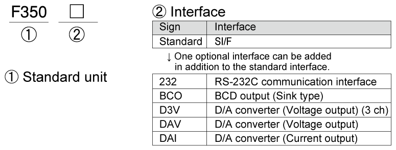
| Interface (Only one option can be installed) |
|
| SIF | 2-wire type serial interface |
|---|---|
| BCO | BCD parallel data output interface (Option) |
| D3V | D/A converter voltage output (3 ch) |
| DAV | D/A converter voltage output (Option) |
| DAI | D/A converter current output (Option) |
| 232 | RS-232C communication interface (Option) |
| General specifications | |
| Power supply voltage | AC 100 V to 240 V +10% -15% (free power source 50/60 Hz) |
|---|---|
| Power consumption | 6 W typ. |
| Operating conditions | Operation temperature: -10 to +40℃, Storage temperature: -40 to +80℃ Humidity: 85% RH or less (non-condensing) |
| Dimensions | 96(W) × 96(H) × 138(D) mm (Not including projections) |
| Weight | Approx. 1.0 kg |
| CE marking certification | EMC directives: EN61326-1 Safety standard: EN61010-1, EN62311 |
| Attachments | |
| AC input cord (Nominal rating 125 V) 3 m | 1 |
|---|---|
| AC input cord converter plug | 1 |
| FCN series I/O connector (with cover) | 1 |
| Ferrite core | 2 |
| Operation manual | 1 |
| Analog I/O connector terminal block (Same accessory as the attached one) |
1 |
| BCD output connector (when BCD output option is selected) |
1 |
| Operating tool (when D/A converter(3 ch) option is selected) |
1 |
| Mini driver (when D/A converter option is selected) |
1 |
Optional accessories
| Model | |
| CA372-I/O | Cable with FCN connector at one-end 3 m |
|---|---|
| CA325AC3P-B3 | AC input cord 3 m |
| CA325AC3P-CEE7/7-B2 | AC input cord (Voltage resistance: 250 V) 2 m |
| CN3P-2P | 3P-2P converter plug for AC input cord |
| CN34 | D-Sub9p connector for RS-232C |
| CN50 | FCN series I/O connector (with cover) |
| CN51 | BCD output connector |
| CN55 | FCN series I/O connector (with diagonal cover) |
| CN73 | D/A converter (3 ch) connector |
| CN81 | Analog I/O connector terminal block (Same accessory as the attached one) |
| DTC2-PSL | Case for F350 |
| GMP96×96 | Rubber packing |
| TSU01 | DC Lighting surge unit |
Please note that there are possibilities of individual differences in a color tone on display devices such as LEDs, fluorescent display tubes and LCDs due to manufacturing process or production lots.
Structure of product code
Download
|
Product catalogue(PDF)
|
⇒Download Page | |
|---|---|---|
|
Operation manual(PDF)
|
||
|
External dimension
|
DXF
(ZIP) |
|
|
PDF
|
||
|
Support tools
|
||
|
Software
|
||
