
Most people, except for engineers, may not be familiar with load cells.
Simply saying, a load cell is a transducer used to measure a force.
This page is for those who know only a little bit about load cells or those who have not heard about it at all.
Relationship between mass and force
2. The Basics of Load Cells
3. Principles of Load Cells
Elastic properties of metals
Strain gauge and bridge circuit
4. Various Types of Load Cells
Types of load cells and loading direction
Temperature effect
Performance and accuracy
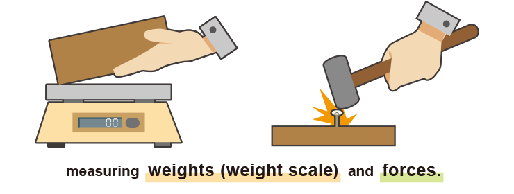
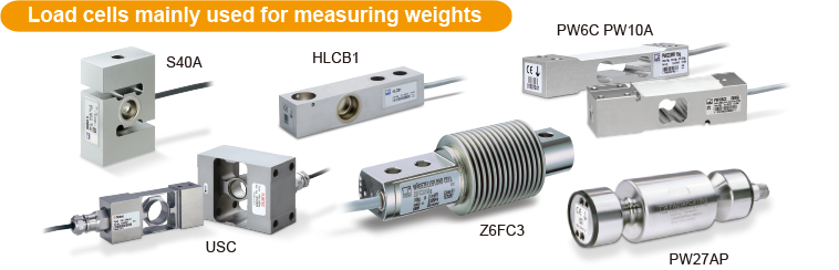
5. Weight and Force Measurements
Weight measurement
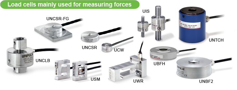
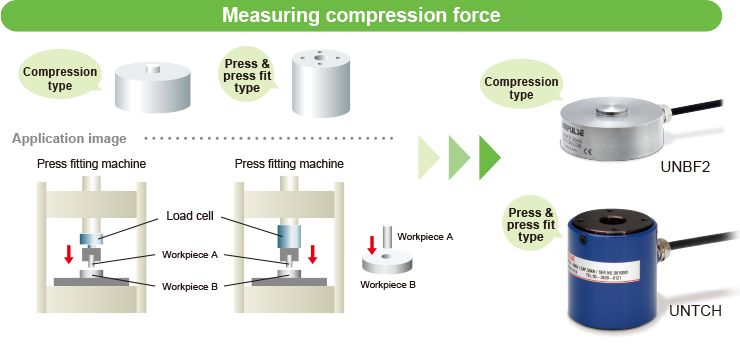
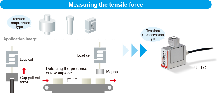
Force measurement
7. Illustrations of Load Cell
Applications
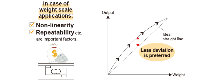
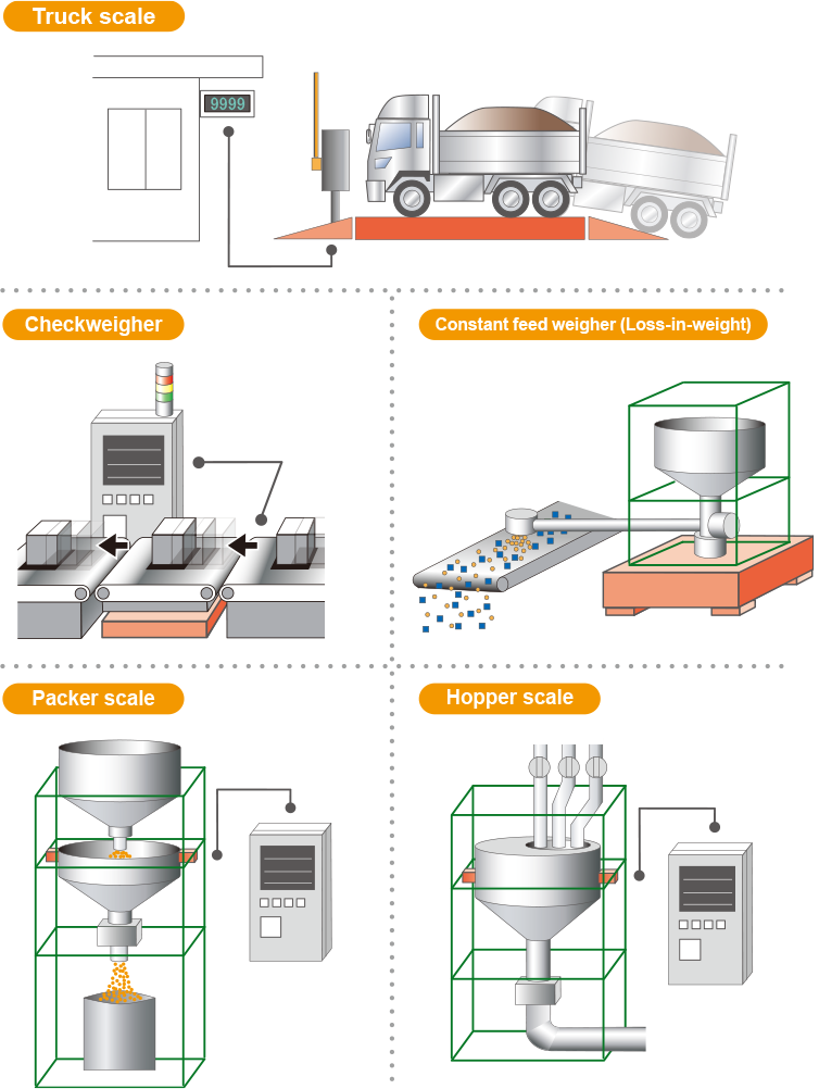
Example of weight scale applications
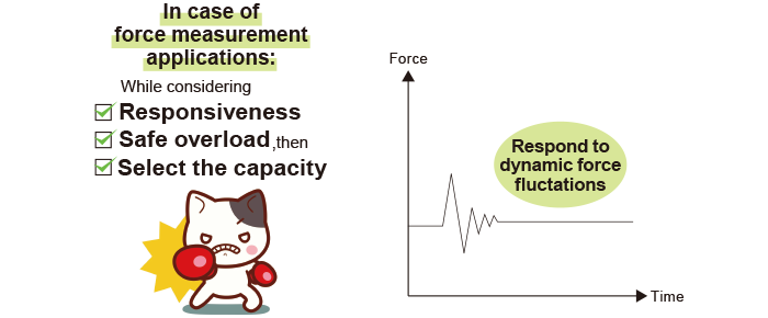
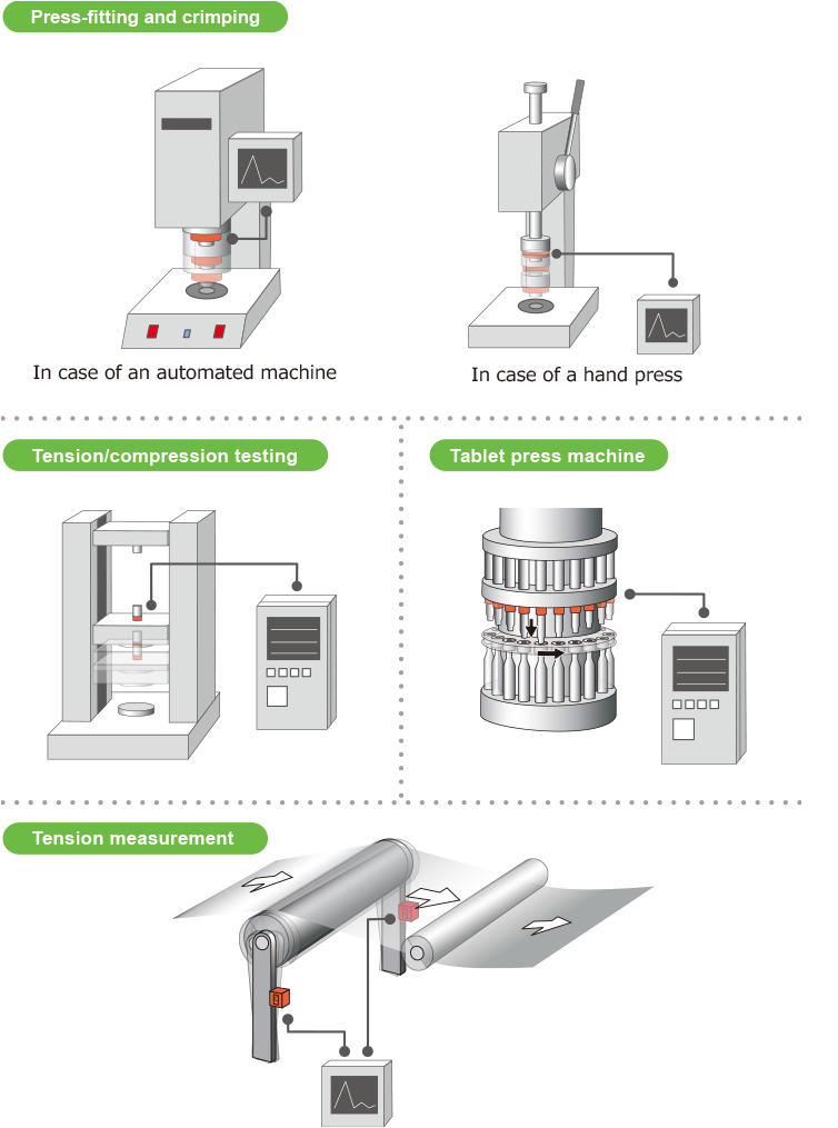
Example of force measurement applications
8. For Safety and More Accurate
Measurements
Common causes of load cell failures
A load cell amplifier is required.
Installation of load cells
Electricnoise countermeasures
9. Glossary
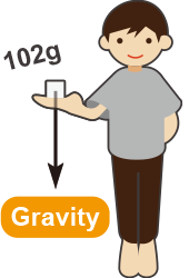
You can feel the weight of the apple when you put it on your hand, as in the picture.
However, the weight felt at this time is not only the mass [kg] of the apple.
At the same time, you can feel the force of the apple trying to fall due to the gravity of the earth.
In other words, measuring weight is measuring force.

The unit of force is called Newton, and is denoted by N.
Relationship between force(F), mass(m) and acceleration(a) is as below.
The acceleration generated by the gravity of the earth is called gravitational acceleration.
The gravitational acceleration varies depending on the location and altitude, but if it is 9.8 m/s2, the force you feel when you place a 102 g object on your hand is:
It will be about 1 N.
(Due to different gravitational acceleration)
For example, in Wakkanai (Hokkaido) and Kagoshima, if a mass of 1 kg is measured with the same calibration scale, there will be a difference of about 1.2 g.
Among many different types of transducers, load cells are one of the sensors most commonly used to measure a force.
Mainly, load cells are used for…
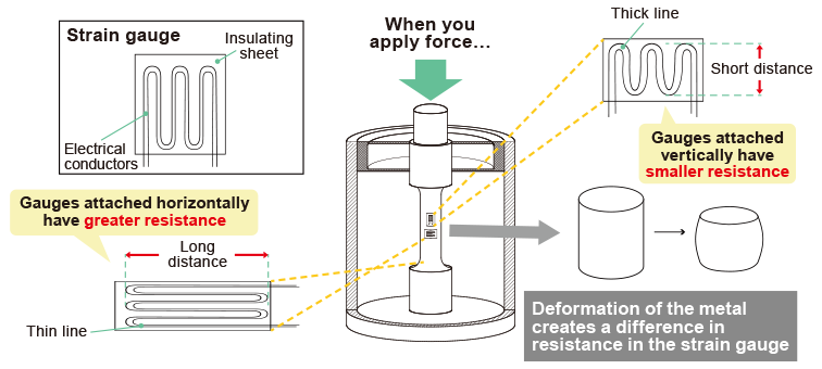
Elastic properties of metals
What happens if you grasp both ends of the metal as shown on the left in the figure below and pull them gradually?
Metal fragments stretch out minute to a certain point and eventually break.
The right-side figure below is a representative graph that shows the process of metal growth in terms of the relationship between force and elongation.
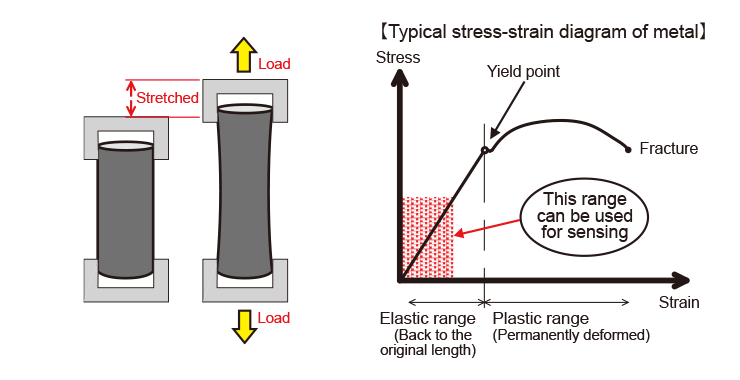
The range before and after the yield point is reached are called “elastic” and “plastic” range respectively.
As you can see in the diagram, the strain is directly proportional to the stress in the elastic range. This range, therefore, can be used as a load sensor.
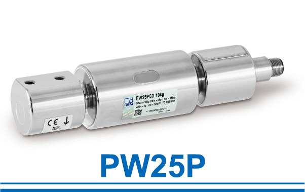
 High wear resistance
Load cell made of special alloy steel with high hardness
(» Go to Product Page)
 Waterproof &
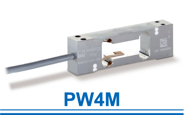 Small size &
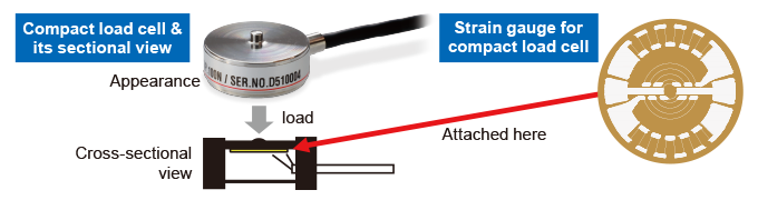
Strain Gauge and Bridge Circuit
Now, we know that metals develop strains directly in proportion to stresses.
Then, as a sensor, how it can be converted to an electrical signal?
Metal foil resistors called “strain gauges” and “bridge circuits” are used for that purpose.
When a resistance difference is created in proportion to the amount of strain of the metal, the voltage output (±SIG) changes, so the force can be measured.
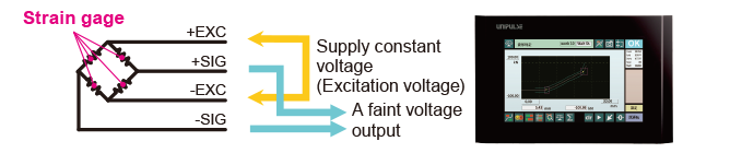
For example, a small compression type load cell uses the following strain gauge:
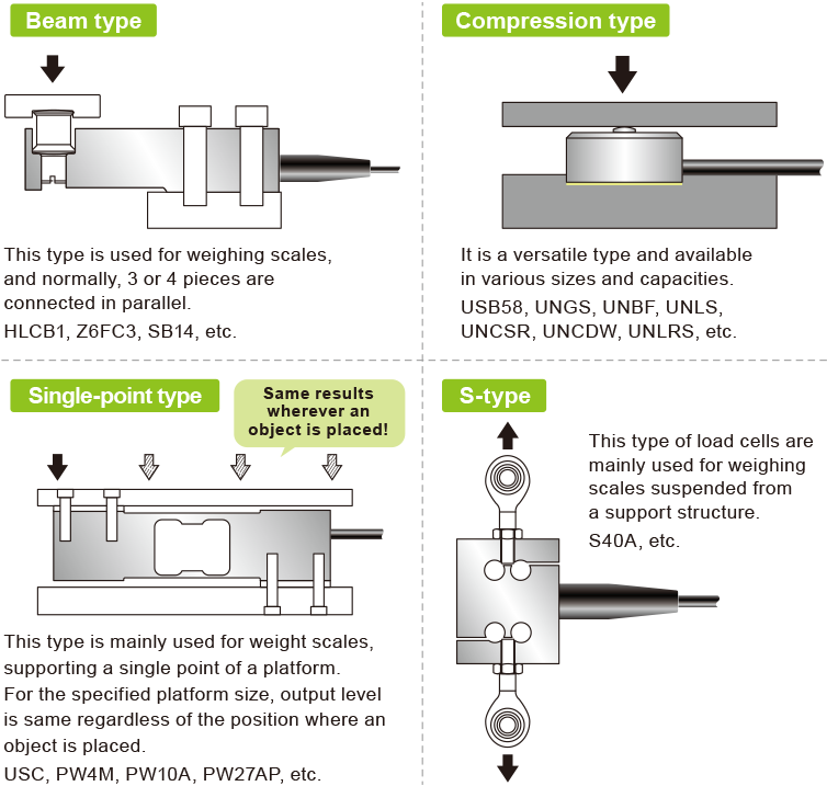
Load cells are available in many different capacities and shapes for measuring weights and forces. Also, it is not uncommon that a special load cell is designed for a specific purpose.
This high adaptability of load cells may be one of the reasons why they are widely used as force sensors.
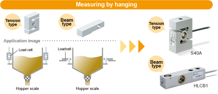
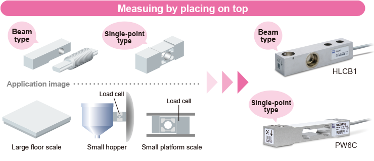
The followings are examples of common load cell types.
Despite high-response, achieves non-linearity, hysteresis, and repeatability of all 1/10000. It can be used as a testing machine or calibration load cell.(» Go to Product Page)

Each load cell is designed to measure a force in specified direction. Though it can tolerate deviations to some extent, it may cause measuring errors if the permissible limit is exceeded.
In the worst case, load cells may be fractured if a force from clearly non-designated direction or over the capacity is applied.
Many transducers are affected by temperature change, and load cells are no exception.
In case high accuracy is required in an environment where the temperature changes, the temperature effects on load cells need to be considered.

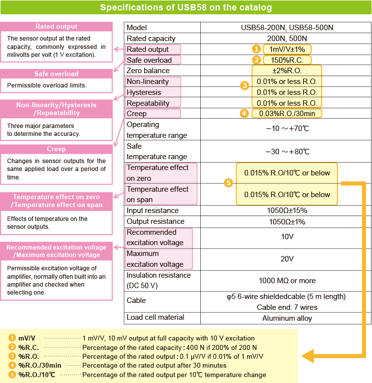
Where can we check to learn the performance and the accuracy of a load cell?
We will explain it using a technical specification sheet listed on our catalogs.
In practice, requirements for load cells are different for each application, and we will explain details later in “6. Load Cell Selection Guide.”
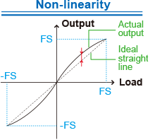 The maximum deviation between ideal straight line and actual output (% FS).
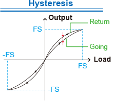 The maximum deviation between going and return
(% FS).
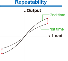 The maximum variation when multiple loads are applied
(% FS).
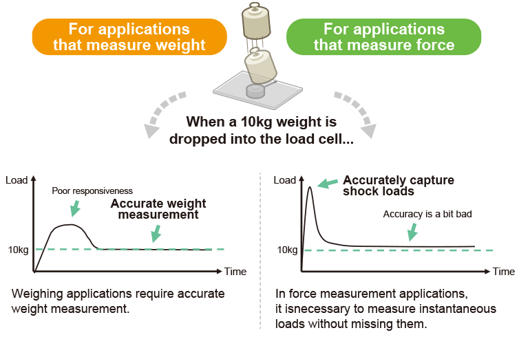
As we mentioned earlier, the two main applications of load cells are measuring weights and forces.
Now, let’s see what difference we can find in requirements on load cells for each application.

In case a load cell is used for a weighing application, higher accuracy may be required.
Thus, characteristics such as non-linearity, repeatability, and even creep in some cases are often given emphasis to when selecting a load cell.

In case a load cell is used for measuring a force, high responsiveness to capture dynamic fluctuations of the force and safe overload are often given emphasis.
The faster the natural frequency is, the higher the responsiveness will become.
In case of force measurement applications, the creep and the hysteresis are not considered too much as important factors.
for both compression & tension
 Available in minute capacities from rated capacity of 1 N.
Even the capacity is small, it has a 500% load capacity and is safe.
(» Go to Product Page)
 High accuracy of 0.03% non-linearity.
Weight measurement
 (
( (
(Force measurement
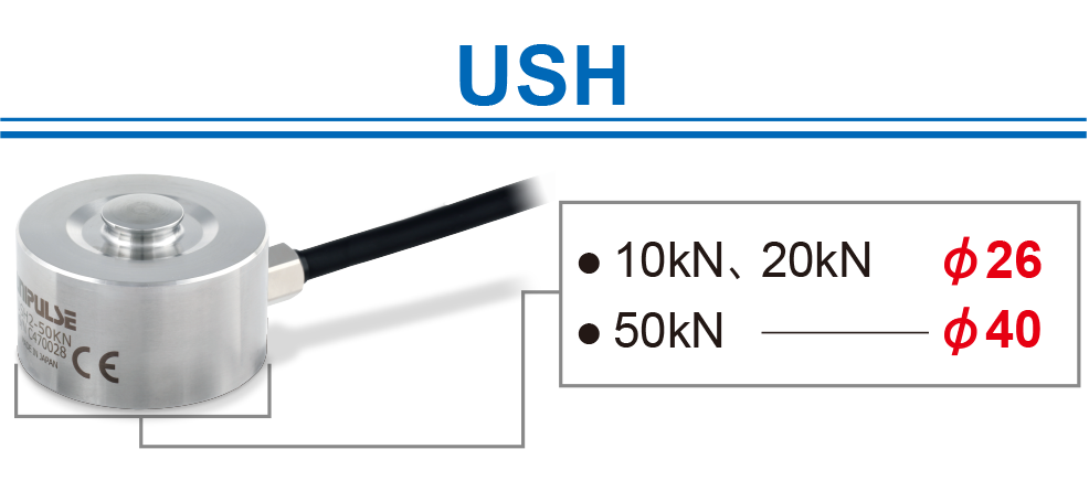
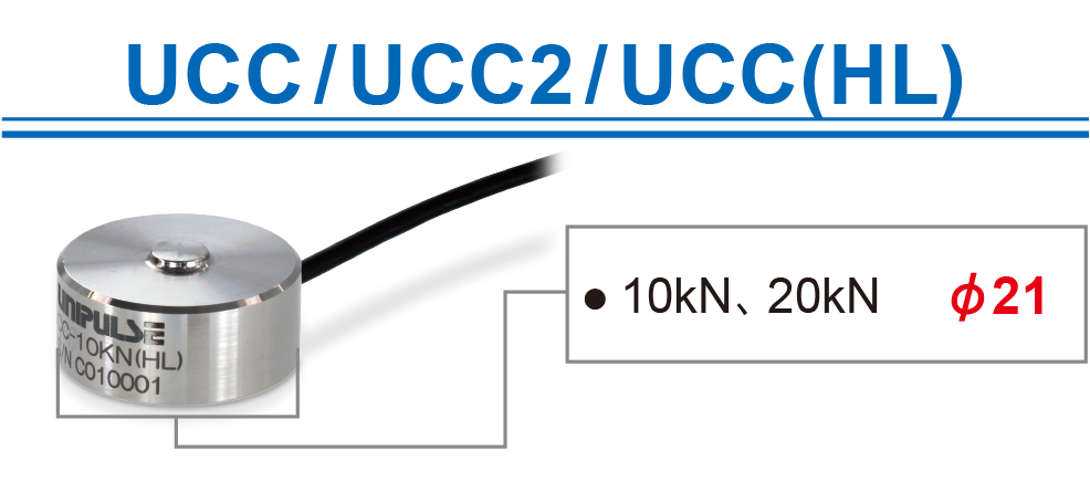
“There is no enough space!” In such a case, please consider USH and UCC.
 (
( (
(Example of weight scale applications
Example of force measurement applications
Common causes of load cell failures
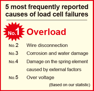
The overwhelming majority is “damage” due to overload.
Not only is the load applied, but there can also be an impact, twisting, or in some cases, an unexpected load due to resonance.
Hence, please consider how many % of the full capacity will be used regularly and see if the required accuracy can be achieved in that condition.
A new load cell born from such voices in the field

A load cell amplifier is required
Since the signal output level is only a few milivolt (very low), a load cell amplifier is required in practice.
The main role of the load cell amplifier is to amplify this weak signal.
In addition, it is common to have a power supply applied to the load cell and a filter function to remove noise components.
Also, there are various types according to the application.

» Go to weighing measurement product page » Go to force measurement product page

Load cell installation
Make sure that the location for load cell installation is sufficiently strong.
It is desirable to protect the installation site so that the load is not applied anywhere other than where it should be applied, and to secure the cable so that it is not pulled.
In addition, in environments where there is dust or water droplets, please check the dustproof and waterproof function of the load cell itself, and protect the load cell as necessary.

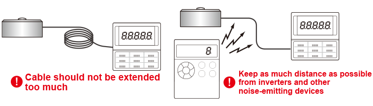
Electric noise countermeasures
The output handled by the load cell is very weak. Depending on the environment, consideration may be required against electrical disturbances.
Especially, in a factory, many other electronic devices are used, and there could be wireless devices emitting radio waves as well.
Extending cables longer than necessary also increases the risk.
| Rated output (R.O.) | Output level obtained by subtracting the output level at no load from the one at rated capacity. Expressed as the output of the excitation voltage per 1 V (mV/V). |
| Rated capacity (R.C.) | Maximum load that can be measured by the transducer while maintaining the specifications. |
| Safe overload | Load which a load cell can withstand without incurring plastic change though specifications are not met. Expressed as a percentage (% R.C.) with respect to the rated capacity. |
| Spring element (beam) | Elements that develop a strain directly in proportion to the level of load. |
| Creep | Changes in output when rated load is applied for a certain period of time and with other conditions. Express rate output as percentage in respect to changes in 30 minutes. (% R.O./30 min) |
| Repeatability | The maximum difference of output signals when the same load is applied repeatedly under the same condition. Expressed as a percentage (% R.O.) with respect to the rated capacity. |
| Hysteresis | The maximum difference of output signals for the same applied load while the load is increased and decreased. Expressed as a percentage (% R.O.) with respect to the rated output. |
| Non-linearity | The maximum deviation from the straight line connecting the no-load point and rated load point on the calibration curve at the time of increasing load. Expressed as a percentage (% R.O.) with respect to the rated output. |
| Zero balance | Output at no-load. Expressed as a percentage (% R.O) with respect to the rated output. |
| Recommended excitation voltage | The most appropriate excitation voltage (V) for the use of the transducer. |
| Insulation resistance | DC resistance between the bridge circuit and the main sensor unit. Normally measured at DC50V (MΩ). |
| Temperature effect on zero | Change in the no-load output (zero balance) due to change in ambient temperature. The change per 10℃ is expressed as a percentage (% R.O./10℃) with respect to the rated output. |
| Temperature effect on span | Change in the rated output due to change in ambient temperature. The change per 10℃ is expressed as a percentage (% R.O./10℃) with respect to the rated output. |
| Maximum excitation voltage | Maximum excitation voltage (V) to be added without changing the characteristics of the transducer. |
| Input resistance | The resistance (Ω) between open input terminals measured at standard test temperature. |
| Strain gauge | An element used to convert strains (resitance changes) to electrical signals. |