


Product outline
Specifications
Analog section|Setting section|I/O section|Display section|General specifications|Attachments
| Analog section | |
| Excitation voltage | DC 10 V±5%, Output current; within 120 mA, remote sense type (Up to 4 load cells at 350 Ω are parallel-connectable.) |
|---|---|
| Zero adjustment range | 0 to 1.5 mV/V for HI gain 0 to 3.0 mV/V for LO gain (digital adjustment) Input of approx. 0.5 mV/V or 1.0 mV/V, Selectable adjust to zero [by dip switch on the rear panel] |
| Gain adjustment range |
2 stages of gain selectable according to the output of load cell [by dip switch on the rear panel] |
| Min. input sensitivity | 0.5 μV/count |
| Accuracy | Non-linearity: within 0.01% FS Zero drift: within 0.2 μV/°C RTI (Typ: 0.15 μV/°C) Gain drift: within 15 ppm/°C (Typ: 7 ppm/°C) Noise: within 0.1 μVp-p RTI (0.1 to 10 Hz) |
| Analog filter | Bessel low-pass filter (-12 dB/oct.) Selectable from 2, 4, 6, 8 Hz |
| A/D converter | Speed: 100 times/sec. Resolution: 16 bit |
| Min. display resolution | 1/10000 |
| Secondary calibration | Calibration can be carried out without an actual load by connecting a resistor to one of the bridges of a load cell. |
| Setting section | |
| Setting method | ・ Keyboard operation (membrane switch with a key click buzzer) ・ External setting is available by installing a setting point option or RS-232C option |
|---|---|
| Setting value storage | ・ Initial set values: NOV RAM (Non-volatile RAM) ・ Other set values: C-MOS RAM with backup of a lithium battery (Effective for more than 7 years depending on usage conditions and storage environment.) |
| Setting value protection | Setting operation can be locked to prevent unauthorized modifications of default values and calibration by malfunction |
| Setting items |
・ Upper Limit/ Lower Limit/ Near Zero/ Set Point 1/ Set Point 2/ CPS/ Over/ Under/ Final |
| I/O section | |
| External output signal | Transistor’s open collector output (Emitter = COM terminal); Output is LO when transistor is ON (Near zero, SP1, SP2, SP3, go or comp, over, under, high limit, Low limit, stable, weight alarm or error, run) |
|---|---|
| External input signal | ON when shorted to COM terminal by TTL-level relay, switch, transistor, or open collector output. (Feed / discharge, tare ON, tare OFF, zero, gross / net, hold or judgment, start, stop) (Drive current: 10 mA or less) |
| Output Conditions | – SP1: Net weight >= final weight-SP1 – SP2: Net weight >= final weight-before final – SP3: Net weight >= final weight-FF – Under: Net weight < final weight-underweight – Over: Net weight > final weight-overweight – Go: Final weight+overweight >= netweight >= final weight-underweight |
| Interface | ・ SIF: 2-wire type serial interface (standard); Interface to link with Unipulse printer or external display. ・ SPI: Interface for set-point units (Optional); Interface to enter various set values via digital switches. ・ BCO: BCD parallel data output interface (Optional): Parallel interface to transmit weight data to a printer, external display, PC or sequencer. ・ 232: RS-232C communication interface (Optional): Write (change)/read weight data, various statuses and setting values from a PC or sequencer. ・ 485: RS-485 communication interface (Optional): Allows longer-distance communication than RS-232C. ID numbers are set, and multiple units of F701 are parallel-connectable. ・ DAC: D/A converter interface (Optional); Interface to convert weight data to current signal and output it. |
| Display section | |
| Display unit | Numerical display (7 digits) with a character height of 18.5 mm by fluorescent display tube |
|---|---|
| Display value | 5 digits, Minus sign displayed on most significant digit |
| Scale capacity | 5-digit numerical values |
| Min. scale division | 1 to 100 |
| Decimal point | Selectable from 0, 0.0, 0.00, 0.000 (with zero blanking function) |
| Over-scale display | Input of A/D converter overflow, Net weight over the set net value, Scale capacity + 9 scale divisions, Gross weight over the set gross weight |
| Center zero | True zero point or the center of each value is displayed. |
| Unit display | Selectable from t, kg, g, N, lb, none |
| Status display | SP3, SP2, SP1, LOCK, ZT, ZALM, STAB, TARE, NET, GROSS, HI LIM, HI, GO, LO, LO LIM, HOLD, NZ |
| General specifications | |
| Power supply voltage | 85 to 110 V, 102 to 132 V, 170 to 220 V, 187 to 242 V AC (Please specify when ordering), 50/60 Hz |
|---|---|
| Power consumption | 15 VA |
| Operating conditions | Operating temperature range -10°C to +40°C; Storage temperature range -20 to +85°C Humidity: 85% RH or less (non-condensing) |
| Dimensions | 192(W) × 96(H) × 160(D) mm (Not including projections) |
| Panel cutout dimensions | 186 +2 -0(W) × 92 +1 -0(H) mm *Installation panel thickness: 1.6 mm or more |
| Weight | Approx. 2.2 kg |
| Attachments | |
| AC input cord (2 m) | 1 |
|---|---|
| Spare fuse (1 A) | 1 |
| Load cell input connector | 1 |
| Control signal I/O connector | 1 |
| Flathead screwdriver | 1 |
| Operation Manual | 1 |
| Set point unit connector (when set point unit option is installed) | 1 |
| BCD output connector (when BCD output option is installed) | 1 |
| D/A converter connector (when D/A converter option is installed) | 1 |
Option
| Model | |
| SPI | Set point unit interface |
|---|---|
| BCO | BCD parallel data output interface |
| 232 | RS-232C communication interface |
| 485 | RS-485 communication interface |
| DAC | D/A converter interface |
Optional accessories
| Model | |
| E780 | Set point unit |
|---|---|
| LB01-NH | Lithium battery (with NH connector) |
| CAAC2P-P2 | AC input cord 2 m |
| CAAC3P-CEE7/7-P1.5 | AC input cord (250 V withstand voltage) 1.5 m |
| CN3P-2P | 3P-2P conversion plug for AC input cord |
| CA4131 | (6-core) cable with JR connector at one end (cable end is separated) 3 m |
| CA4230 | JR-PRC conversion relay (6-core) cable 0.3 m |
| CA4311 | JR-PRC conversion relay (6-core) 4-wire type/6-wire type (for 520 A) 1 m |
| CA7 | Coaxial cable with BCN on both ends 1.5 m |
| CA8 | BNC-alligator clip cable 1.5 m |
| CA3150 | Flexible flat cable with 57 F 36 pins at both ends |
| CN21 | 57 series 36p connector for BCD output/set point unit |
| CN23 | 57 series 24p connector for external input/output |
| CN35 | D-sub 25p connector for RS-232C |
Please note that there are possibilities of individual differences in a color tone on display devices such as LEDs, fluorescent display tubes and LCDs due to manufacturing process or production lots.
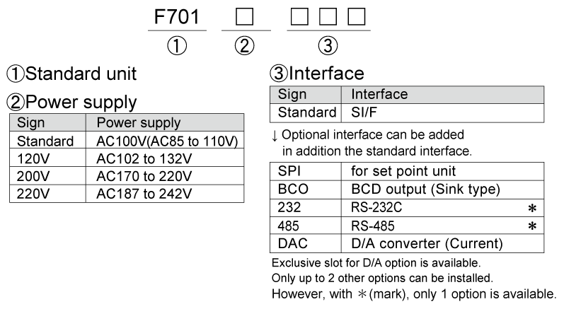
Structure of product code
Download
|
Product catalogue(PDF)
|
⇒Download Page | |
|---|---|---|
|
Operation manual(PDF)
|
||
|
External dimension
|
DXF
(ZIP) |
|
|
PDF
|
||
|
Support tools
|
||
|
Software
|
||
