


Product outline
F377A is a digital indicator integrated with a voltage / current output type sensor that can display physical quantities such as pressure, load and torque in waveforms. It can be connected to the voltage of ±10 V and the current of ±20 mA. It is able to visually capture in waveforms the fluctuations in physical quantities which are difficult to capture by only numerical values.
With a maximum 2000 times per second for high-speed processing, it is also ideal for narrow value fluctuations and comes equipped with a HI/LO limit comparison function, various hold functions and judgment function.
F377A is the best digital indicator for graders and testers used in results judgment of assembling work and auto machining.
Specifications
Analog section|Display section|Setting section|Hold section|Comparison function|Calibration value selection|External signal|Interface|General specifications|Attachments
| Analog section | |
| Voltage input | -10 to +10 V, Input impedance 1 MΩ or more |
|---|---|
| Current input | -20 to +20 mA, Input resistance Approx.250 Ω |
| Accuracy |
Non-linearity: within 0.02% FS±1 digit (at a 10 V or 20 mA input) Zero drift: within 0.2 mV/℃ RTI or within 0.4 μA/℃ RTI Gain drift: within 0.01%/℃ |
| Analog filter | Low pass filter (-6 dB/oct.) Selectable at 30, 100, 300, 1000 Hz |
| A/D converter |
Speed: 2000 times/sec. Resolution: 24 bit (binary) Effective resolution: Approx. 1/30000 to 10 V or 20 mA input |
| Analog monitor output | Output level: Approx. 0.6 V per 1 V input or approx. 0.3 V per 1 mA input Load resistance: 2 kΩ or higher |
| Display section | |
| Display unit | TFT color LCD module 3.5 inch |
|---|---|
| Display area | 71(W) mm × 53(H) mm |
| Dot structure | 320 × 240 dot |
| Measured value | 5 digits: -99999 to +99999, Sign: Minus sign on most significant digit |
| Setting section | |
| Comparison functions | HH, Hi, Lo, LL, Hysteresis, alarm Hi, alarm Lo, near zero, comparison timing, comparison output selection |
|---|---|
| Hold setting | Hold mode, detection start level, detection time, level detection condition, sample point shift value, detection end level, average sample number, inflection point judging value, pre-inflection point slope detection time, post-inflection point slope detection time, inflection point shift, detection start condition, peak-valley detection min. value, peak-valley detection amplification |
| Graph setting | Graph mode, Y-axis (load) start point, Y-axis (load) end point, X-axis (time) end point, plotting start level, interval time, plotting start level conditions |
| Calibration setting | Analog input selection, zero calibration, equivalent input calibration, actual load calibration, calibration value selection, unit, minimum scale, digital offset, digital zero limit |
| Operation setting | Digital filter, analog filter, backlight lighting time, language change, SI/F print, motion detect, zero tracking, monitor output filter, display color of measured value, B5 function selection, B6 OFF detection standby time, B8 OFF detection standby time, measured work input change, control input change, password |
| RS-232C setting | Communication mode, baud rate, character length, stop bit, parity bit, delimiter, flow control |
| Extended comparison function | Previous value comparison, relative value comparison |
| Extended hold function | Double hold, auto reset change, hold value update, sample trigger change, hold cancel at DZ, hold END timing |
| Extended graph function | Pre-trigger display |
| Extended operation function | Digital filter characteristics, average time at DZ, RUN output format |
| Extended option | BCD output data format |
| Hold section | |
| Hold | 1) Sample, 2) Peak, 3) Valley, 4) P-P, 5) Average, 6) Inflection Point, 7) Relative Maximum, 8) Relative Minimum, 9) Relative Difference, 10) Sample & Peak, 11) Sample & Valley, 12) Sample & P-P, 13) Sample & Average, 14) Sample & Inflection Point, 15) Sample & Relative Maximum, 16) Sample & Relative Minimum, 17) Sample & Relative Difference, 18) Peak & Valley, 19) Peak & P-P, 20) Valley & P-P, 21) Average & Peak, 22) Average & Valley, 23) Average & P-P, 24) Relative Maximum & Relative Minimum, 25) Relative Maximum & Relative Difference, 26) Relative Minimum & Relative Difference |
|---|---|
| Comparison function | |
| Can set 4 different settings from Hi limit, Lo limit, etc | |
| Calibration value selection | |
| Stores up to 4 types of calibration value that can be interchanged | |
| External signal | |
| External output signal (8 points) | HI/LO comparison output (HH, HI, OK, LO, LL)/ RUN output/ hold end output/ graph plotting end output Vce = 30 V (max), Ic = 30 mA (max) |
|---|---|
| External input signal (10 points) | Work selection input/ hold control input/ digital zero input (DZ)/ graph plotting control input/ calibration selection input lc = 10 mA or lower |
| Interface | |
| SIF | 2-wire type serial interface |
|---|---|
| 232 | RS-232C communication interface |
| BCO | BCD parallel data output interface (Sink type)(Option) |
| DAV | D/A converter voltage output (Option) |
| DAI | D/A converter current output (Option) |
| CCL | CC-Link interface (Option) |
| General specifications | |
| Power supply voltage | DC 24 V (±15%) |
|---|---|
| Power consumption | 4 W typ. |
| Operating conditions | Operation temperature: -10℃ to +40℃ Storage temperature: -20℃ to +60℃ Humidity: 85% RH or lower (non-condensing) |
| Inrush current (typ) | 55 A, 1 msec (cold start at room temperature) |
| Dimensions | 96(W) × 96(H) × 138(D) mm (Not including projections) |
| Weight | Approx. 1.0 kg |
| Attachments | |
| FCN series I/O connector (with cover) | 1 |
|---|---|
| Jumper wire | 1 |
| Operation manual | 1 |
| Analog I/O connector terminal block (Already mounted on the main unit) |
1 |
| BCD output connector (when BCD output option is installed) | 1 |
| Mini screwdriver (when D/A converter option is installed) |
1 |
| CC-Link connector (when CC-Link option is installed) |
1 |
Option
| Model | |
| BCO | BCD parallel data output interface |
|---|---|
| DAV | D/A converter voltage output |
| DAI | D/A converter current output |
| CCL | CC-Link interface |
Optional accessories
| Model | |
| CA372-I/O | end treatment 24-leads cable with FCN connector at one end 3 m |
|---|---|
| CA81-232X | miniDIN-D-Sub9p cross cable 1.5 m |
| CN50 | FCN series I/O connector (with cover) (Same accessory as the attached one) |
| CN55 | FCN series I/O connector (with diagonal cover) |
| CN60 | Circular DIN 8p connector for RS-232C |
| CN51 | BCD output connector |
| CN71 | CC-Link connector |
| CN80 | Analog I/O connector terminal block (Same accessory as the attached one) |
| GMP96 × 96 | Rubber packing |
Please note that there are possibilities of individual differences in a color tone on display devices such as LEDs, fluorescent display tubes and LCDs due to manufacturing process or production lots.
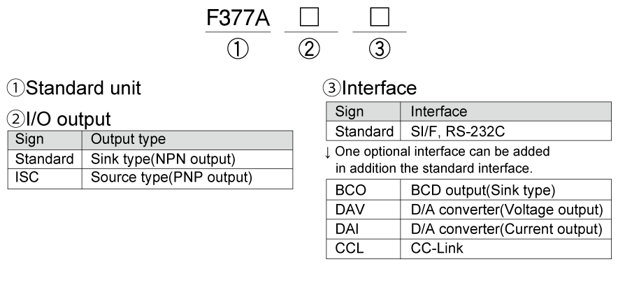
Structure of product code
Download
|
Product catalogue(PDF)
|
⇒Download Page | |
|---|---|---|
|
Operation manual(PDF)
|
||
|
External dimension
|
DXF
(ZIP) |
|
|
PDF
|
||
|
Support tools
|
||
|
Software
|
||
