


Product outline
F381A is a dynamic force processor integrated with a strain gauge sensor that can display physical quantities such as pressure, load and torque in waveforms. It is able to visually capture in waveforms the fluctuations in physical quantities which are difficult to capture by only numerical values.
- 4000 times/sec. high-speed processing
- Analog monitor output
- Variety of interfaces
- 3.5-inch color LCD module & touch panel
- Excellent operability
- I/O Input: Plus common / Minus common shared
Voltage output is proportionate to the input signal making the recording on recorder convenient.Approx. 2 V per 1 mV/V strain gauge input
RS-232C / CC-Link / DeviceNet /Ethernet
Operation can be effortlessly performed by a direct touch on the touch panel.
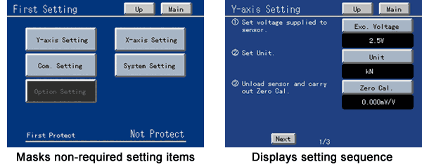
F381A is right-down demanding on straightforwardness and is therefore made able to automatically mask non-required setting items and also to display setting in the required sequence when that particular set item has specific setting sequence.
I/O Output: Sink type / Source type selectable.
It can be connected to various types of external equipments such as PLCs.
Excellent operability
F381A is no nonsense and straightforward and is made able to automatically mask non-required setting items and also to display a setting in the required sequence when that particular setting item has a specific setting sequence.
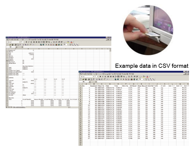
Saves measurement data in an SD card
Measurement data and set values can be logged (recorded) in the SD card. Such data can be retained as 100% recorded quality data or be used when setting up equipment or when performing cause analysis or improvement of problems. The data can be easily converted to CSV format and is therefore easily edited in Microsoft Excel or the like.
Comparison & Hold Function by Waveform Display
These functions are used to judge the acceptability of measurement waveforms.
Depending on type of applications, Waveform Comparison Function and Multi Hold Function can be jointly utilized for judgment.
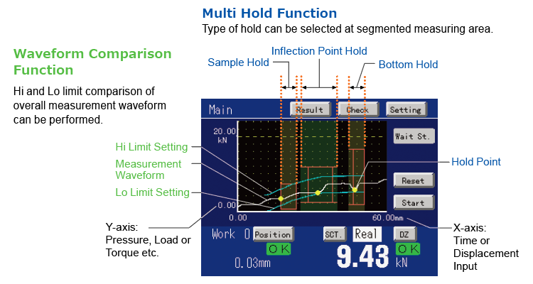
Waveform comparison function
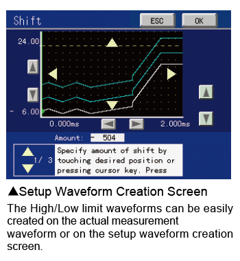
This function compares the actual measurement waveform against the setup High/Low limit waveforms and will give out an NG judgment when any of the point exceeded the preset High/Low limit waveforms.
As it compares the overall measurement waveform, accurate judgment can be made even applications that are unable to narrow down its judgment points.
Multi hold function
After the measuring range is segmented, judgment is carried out while the type of hold (sample, peak, bottom, P-P, Average, max, min, inflection point, End Displacement) is interchanged as set.
The multi hold function can specify the Hi/Lo limit value and type of hold at each of the segmented range. Multipoint judgment is possible because the multi hold function is capable of using the peak hold to detect the inhibit timer immediately after the press-fit is started and then uses the inflection point hold to judge the load just before the ramming is commenced.
Displacement input as a standard equipment
It performs 2-dimensional waveform comparison & multi hold through its dual input from the displacement sensor and strain gauge sensor. On X-axis, voltage or pulse input can be connected while on Y-axis, strain gauge sensor can be connected. This is highly effective for applications which are difficult to control only by time factor such as the control for pressing time of press machines and for the imposing time on works with indivisual differences.
* When nothing is connected with X axis, Waveform Comparison & Multi Hold by the time series can be done.
* The voltage input is an option.
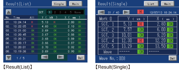
Comparison results display
The comparison results of Waveform Comparison Function and Multi Hold Function can be verified on the display.【Result(List)】(An individual display) and 【Result(Single)】(a list display) to selection is possible. (Latest 40 data)
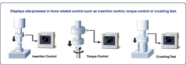
Application example
Specifications
Sensor input for load|Display|Measurement functions|External signal|SD card|Interface|Option|General specification
| Sensor input for load (strain gauge input fixed) | |
| Excitation voltage | DC 10 V, 2.5 V ±10% (Depending on setting) Output current: within 30 mA |
|---|---|
| Signal input range | -3.0 mV/V to +3.0 mV/V |
| Accuracy |
Non-linearity: within 0.02% FS±1 digit (at 3.0 mV/V input) Zero drift: within 0.5 μV/℃ RTI Gain drift: within 0.01%/℃ |
| Analog filter | Low pass filter (-6 dB/oct.) Selectable from 10, 30, 100, and 300 Hz |
| A/D converter |
Speed: 4000 times/sec. Resolution: 24 bit (binary) Effective resolution: Approx. 1/30000 to 3.0 mV/V |
| Analog voltage output |
Output level: Approx. 2 V per 1 mV/V input Load resistance: 2 kΩ or more |
| Sensor input for displacement (Standard: pulse input open collector) Option: Pulse Input (Line Driver [LDI]) |
|
| Maximum input frequency | 50 kHz |
|---|---|
| Internal counting range | Approx. 1,000,000 |
| Adaptable rotary encoder |
Output: Incremental type 2-phase output (A/B signal output) Also capable of single-phase output (A-phase input used. All pulses are counted as in the plus direction.) Output stage circuit specification: Open collector (NPN type, Vceo = 30 V or more, Ic = 30 mA or more) Output stage circuit specification(LDI): Line driver(Based on RS-422) |
| Sensor input for displacement (Option: Voltage input [VIN]) | |
| Signal input range | -5 V to +5 V |
|---|---|
| Input impedance | Approx. 10 MΩ |
| Zero adjustment range | -5 to +5 V Automatic adjustment by digital processing |
| Equivalent input calibration range | -5 to -1 V, +1 to +5 V |
| Equivalent input calibration error | Within 0.1% FS |
| Actual calibration range | -5 to +5 V * In Approx. −0.01 to +0.01 V, a zero calibration point to calibration is impossible. |
| Accuracy |
Non-linearity: within 0.02% FS±1 digit (at 5 V input) Zero drift: within 50 μV/℃ RTI Gain drift: within 0.02%/℃ |
| Analog filter | Low-pass filter (-6 dB/oct.) Selectable from 10, 30, 100, and 300 Hz. |
| A/D converter |
Speed: 4000 times/sec. Resolution: 24 bits (binary) Effective resolution: Approx. 1/30000 to 5 V |
| Display | |
| Display | TFT color LCD module Display area: 71(W) × 53(H) mm Dot configuration: 320 × 240 dot |
|---|---|
| Indicated value |
Load: -9999 to +9999 Displacement: -9999 to +32000 Decimal place: Selectable display position from 0.000, 0.00, 0.0, 0 |
| Display frequency | Fixed at 3 times/sec. |
| Measurement functions | |
| Multihold mode 16 ch (setting values can be stored) |
Measuring range can be segmented and changeover to any hold for judgment can be performed. Sample, Peak, Bottom, P-P, Relative Maximum, Relative Minimum, Inflection Point, Average, End Displacement |
|---|---|
| Waveform comparison mode 16 ch (setting values can be stored) |
Compares the actually measured waveform against the preset Hi / Lo waveforms. The overall measured waveform will be compared against thepreset Hi / Lo and if any of its points exceeds the preset waveform, then the measured waveform will be NG. |
| External signal | |
| Output signals 16 points |
Output type:Sink type/ Source type selectable. (Source type is optional [ISC].) Output transistor ON at signal ON. To connect an input unit like a PLC, connect plus common for sink type, and minus common for source type. Rated voltage: 30 V, Rated current: 30 mA Isolation: Photocoupler |
|---|---|
| Input signals 16 points |
Input type: Plus common/ Minus common shared To connect a transistor, connect NPN output type (sink type) for plus common and PNP output type (source type) for minus common. ON Voltage: 12 V or more, OFF Voltage: 3 V or less, At 24 V load: approx. 5 mA Isolation: Photocoupler |
| SD card | |
| SD card slot | All parameters can be preserved and reconstructed. All comparison waveforms can be preserved and reconstructed. Measurement waveforms and judgment points can automatically be preserved. * An SD card of 1 GByte is attached. 1 MByte for storage capacity of up to 80 waveforms. |
|---|---|
| Interface (Only one interface option can be installed.) |
|
| [232] RS-232C communication interface |
Start/stop system Baud rate: 1200 bps to 38400 bps All parameters can be read and written. All comparison waveforms can be read and written. Measurement waveforms and judgment points can be read. |
|---|---|
| [CCL] CC-Link interface (option) |
Directly linkable with a Mitsubishi (multipurpose) sequencer. All parameters can be read and written. Judgment points can be read. |
| [ODN] DeviceNet interface (option) |
Connectable with DeviceNet-compliant OMRON CompoBus/D seamlessly. All parameters can be read and written. All comparison waveforms can be read and written. Measurement waveforms and judgment points can be read. |
| [ETN] Ethernet interface (option) |
All parameters can be read and written. Measurement waveforms and judgment points can be read. |
| Option | |
| [LDI] Pulse input (line driver) |
It can be connected with Line driver output-type sensor (Incremental type) in accordance with RS-422 like the contact-type, eddy current-type or laser-type etc.. |
|---|---|
| [VIN] Voltage input |
±5 V voltage output type sensor of the contact type, eddy current type, laser type, etc., can be connected. |
| [ISC] I/O sourrce boad |
Output type: sourrce type To connect an input unit like a PLC, connect minus common. |
| General specification | |
| Power supply voltage | DC 24 V (±15%) |
|---|---|
| Power consumption | 6 W typ. |
| Inrush current (Typ.) | 2 A, 10 msec (cold-start at room temperature) |
| Operating conditions | Operation temperature : -10 to +40℃ Storage temperature : -20 to +60℃ Humidity: 85% RH or less (non-condensing) |
| External dimensions | 96(W) × 96(H) × 117.3(D) mm (Not including projections) |
| Weight | Approx. 1.0 kg |
Attachments
| Attachments | |
| FCN series I/O connector (with cover) | 1 |
|---|---|
| Operation Manual | 1 |
| SD card 1 GByte | 1 |
| Analogue I/O connector terminal block (Already mounted on the main unit) |
1 |
| CC-Link connector (when CC-Link option is selected) | 1 |
| DeviceNet connector (when DeviceNet option is selected) | 1 |
Optional accessories
| Model | |
| DTC1 | Case for F381A (with AC power supply) |
|---|---|
| SD1G | SD card 1 GByte(Same as the attachment) |
| SD2G | SD card 2 GByte |
| CA81-232X | miniDIN-D-Sub9p cross cable 1.5 m |
| CN52 | FCN series I/O connector (with cover)(Same as the attachment) |
| CN57 | FCN series I/O connector (with diagonal cover) |
| CN60 | Round DIN 8p connector for RS232C |
| CN71 | CC-Link connector |
| CN72 | Double row connector for CC-Link |
| CN81 | Analogue I/O connector terminal block (Same as the attachment) |
| CND01 | DeviceNet connector |
| GMP96×96 | Rubber packing |
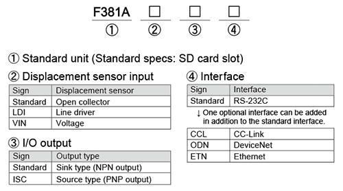
Structure of product code
Please note that there are possibilities of individual differences in a color tone on display devices such as LEDs, fluorescent display tubes and LCDs due to manufacturing process or production lots.
Download
|
Product catalogue(PDF)
|
⇒Download Page | |
|---|---|---|
|
Operation manual(PDF)
|
||
|
External dimension
|
DXF
(ZIP) |
|
|
PDF
|
||
|
Support tools
|
||
|
Software
|
||
