


Product outline
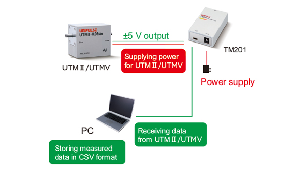
- Variations of torque, rpm, and power can be monitored and saved on PC.
(Application software can be downloaded from our website for free) - Maximum, minimum, and average value can be displayed.
- Measurement (numeric) data is automatically saved in CSV format.
- The unit supplies operation power to UTMⅡ/UTMV.
- Two cables are attached: one for UTMⅡ/UTMV and the other for PC.
Application software for USB interface
・ Display real-time data sent from UTMⅡ/UTMV via USB0.
・ Torque, rotation speed, power and time in the graph can be specified by cross-lines.
・ Measurement(numeric) data is automatically saved in CSV format.
・ Easy calibration with simple selection of sensor types and display conditions!
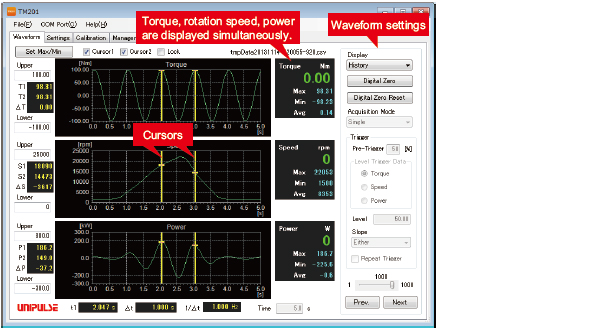
■ Display mode
[Normal]
In-progress waveform data will be displayed.
Maximum, minimum, and average value of the waveform data will be displayed.
1. Single
After “start” button is pressed, data will be recorded once for pre-set time period.
2. Continuous
“Single” mode operation will be repeated in cycle until “stop” button is pressed.
3. Level trigger
After “start” button is pressed, it will be put on standby for a trigger.It starts to import the data when the input level goes over the trigger level.
[History]
Previous waveform data can be displayed (up to 1000 files of waveform data can be saved).
■ Trigger options
・Pre-trigger ・Level trigger data ・Trigger level
・Trigger slope ・Repeating trigger
■ Cursors (max.: two)
Torque readings at cursor positions and difference between those two readings will be displayed.
Example of use
* PC and special software are required to use the TM201.
Application software for the USB interface option can be downloaded from this page.
Specifications
Torque sensor input|Pulse input for rpm|Power supply for UTMⅡ/UTMV|Display section|Interface|General specifications|Attachments
| Torque sensor input (voltage input) | |
| Signal input range | -5 to +5 V Input impedance : 1 MΩ or more |
|---|---|
| Accuracy | Non-linearity : Within 0.02% FS±1 digit Zero drift : Within 0.2 mV/℃ RTI Gain drift : Within 0.01%/℃ |
| Analog filter | Primary low-pass filter 1 kHz (fixed) |
| Digital filter | Secondary low-pass filter fc = 3 Hz, 30 Hz, 300 Hz, OFF (variable) |
| Data output rate | Speed : 300 times/sec. Resolution : 24 bit (binary) Approx. 1/30000 with respect to 5 V |
| Pulse input for rpm (input for open collector type) | |
| Maximum input frequency | Conforming to the maximum rotation speed of UTMⅡ/UTMV |
|---|---|
| Minimum input frequency | Selectable from 15, 10, 5, 3, or 2 rpm (when pulse rate is 4 ppr) Selectable from 60, 40, 20, 12, 8 or rpm (when pulse rate is 1 ppr) |
| Minimum pulse width | 50 μs |
| Circuit layout | No-voltage (dry) contact input (minus common): open collector outputs can be connected (Ic = approx. 10 mA) |
| Power supply for UTMⅡ/UTMV | |
| Power supply | DC 24 V (UTMⅡ/UTMV 1 unit) |
|---|---|
| Display section | |
| LED status light | LED (Red) : power supply/alarm status LED (Green) : UTMⅡ/UTMV is operating normally |
|---|---|
| Interface | |
| Interface | USB |
|---|---|
| General specifications | |
| Power supply | AC 100 V to 240 V (+10%-15%) (free power source 50/60 Hz) * When supplied AC adapter is used. |
|---|---|
| Power consumption | 4 W typ. (AC adapter) |
| Operating | Operation temperature : 0℃ to +40℃ Storage temperature : -10℃ to +60℃ Humidity : 80% RH or less (non-condensing) |
| Dimension | 50(W) × 23(H) × 80(D) mm (Not including projections) |
| Weight | Approx. 120 g |
| Attachments | |
| Setup guide | 1 |
|---|---|
| AC adapter for TM201 1.8 m | 1 |
| Cable for UTMⅡ/UTMV connection 2 m | 1 |
| USB cable (Type-A-Bmini) 1.8 m | 1 |
Optional accessories
| Model | Description |
| CA81-USB | USB cable (Type-A-Bmini) 1.8 m (same as attachment) |
|---|---|
| CATM21-M | Cable for connecting UTMⅡ/UTMV 2 m (same as attachment) |
| CATM51-M | Cable for connecting UTMⅡ/UTMV 5 m |
| CN90 | Waterproof plastic connector for UTMⅡ/UTMV |
| TM201 AC PIN EU | Switching AC PIN(EU) |
Please note that there are possibilities of individual differences in a color tone on display devices such as LEDs, fluorescent display tubes and LCDs due to manufacturing process or production lots.
Download
|
Product catalogue(PDF)
|
⇒Download Page | |
|---|---|---|
|
Operation manual(PDF)
|
||
|
External dimension
|
DXF
(ZIP) |
|
|
PDF
|
||
|
Support tools
|
||
|
Software
|
||
