


Product outline
Easy operation that only closing the sensor probe to the target surface.
The calibration of the surface reflectivity is not required.
Features of ATW200
- Fast response up to 3 MHz bandwidth! Best suited for ultrasonic vibrator and high-frequency vibration measurement.
- Extra-high resolution for the nanometer measurement capability! Since it is truly for displacement measurement, rather than speed measurement, even a small displacement at low frequency can be detected as well.
- The variable low-pass filter is available! The ideal balance between the high response speed and high resolution can be achieved.
- Easy setup! By putting sensor near the target, only one time is needed for calibration of reflectance.
Principle of ATW200
ATW200 is a differential fiber-optic displacement sensor! With our unique arrangement of optic fibers (patent granted), nanometer-order resolution and responsiveness of 3 MHz are achieved, and influence by reflectance of the measured target is suppressed.
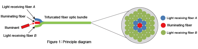
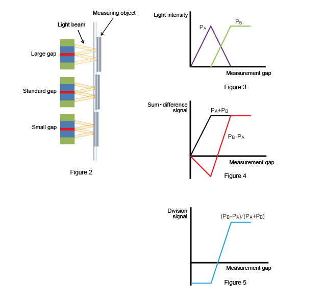
As shown in Figure 1, fiber optic bundle is splitted into 3 branches, each connecting to the opposite side of the illuminating fiber, light receiving fiber A and light receiving fiber B placed at the measurement terminal. When the light from light source is projected diagonally onto the illuminating fiber, the light will be reflected from the suface of measuring object as shown in Figure 2 onto the light receiving fiber. At that moment, the reflected light will form a ring shape, and its diameter varies according to the measurement gap. The amount of light projected onto the light receiving fiber is labeled as PA and PB, and the changes are shown in Figure 3. In Figure 4, the sum of signal PA+PB is the total light reflected, whereas the difference between signal PB-PA changes according to the gap. The signal obtained through division of the difference and sum signals is irrelevant to the reflectance of the measuring object. (Figure 5)
Application example
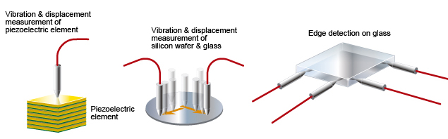
Ideal for the high-speed micro-displacement measurement (e.g. scanning probe microscope cantilever, piezoelectric elements, LCD glass, vibration analysis of glass disk, etc…).
Specifications
Amplification unit|Plug-in module|Resolution example
| Amplification unit | |
| Model | ATW200 |
|---|---|
| Principle | Differential fiber-optic type |
| Responsivity(Hz) Available response frequency |
100, 1 K, 10 K, 100 K, 1 M, PASS (3 M) |
| Variable magnification |
×1, ×2, ×5, ×10, ×20, ×50 |
| Display | 4 and 1/2 digit digital voltage meter |
| Analog output | ±10 V |
| Operating voltage | AC 100 V 50/60 Hz or DC 24 V 1.2 A |
| Operating conditions | 0 to 45℃ 20 to 85%RH (non-condensation) |
| Plug-in module | |||
| Module No. | ATP201 | ATP202 | ATP203 |
|---|---|---|---|
| Illuminant | SLD (super luminescent diode)(λ = 830 nm) | ||
| Fiber length | 1 m (standard) | ||
| Outer diameter of probe tip (mmφ) | 1.2 | 3.0 | 1.2 |
| Operating temperature range of probe tip* | 0 ~ 150℃ | 0 ~ 70℃ | 0 ~ 150℃ |
| Measuring spot diameter (mmφ) | Approx. 0.3 | Approx. 1.5 | Approx. 0.3 |
| Measurement range (μm) | Approx. 20 | Approx. 300 | Approx. 12 |
| Operating range (μm) | Approx. 80 | Approx. 700 | Approx. 50 |
| Sensitivity (μm/V) | Approx. 2 | Approx. 30 | Approx. 1.3 |
| * It is the temperature range that the probe can tolerate, but the accuracy is not guaranteed. | |||
| Resolution example (If the measuring object is a block gauge) | |||
| Cutoff frequency | ATP201 Resolution (nmrms) | ATP202 Resolution (nmrms) | ATP203 Resolution (nmrms) |
|---|---|---|---|
| 3 MHz | 12 nm | 1.2 μm | 2.5 nm |
| 1 MHz | 7 nm | 1 μm | 2.3 nm |
| 100 kHz | 1.6 nm | 0.3 μm | 1.0 nm |
| 10 kHz | 0.7 nm | 0.2 μm | 0.5 nm |
| 1 kHz | 0.6 nm | 0.2 μm | 0.4 nm |
| 100 Hz | 0.5 nm | 0.2 μm | 0.3 nm |
| Resolution will change according to the reflectance of measuring object. | |||
● We can also custom-made the fiber probe (e.g. extension in length, bent-tip type, etc…).Please contact us if you need that.
● The above characteristics are typical values.A difference may occur because of the variability in the sensor probe production.
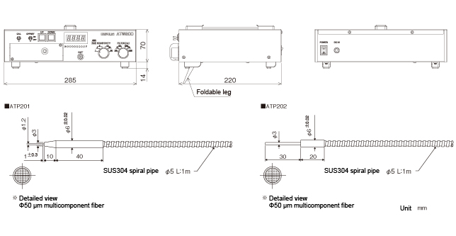
External dimension
Use image
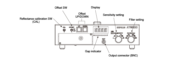
Hold the probe closer to the measuring object and turn ON the reflectance calibration SW. Numerical values will disappear from the display as it enters calibration mode. Follow the instructions from the display and adjust the measurement gap to the specified range. When calibration is completed, the ATW200 will return to measuring mode and the numerical value will be displayed.
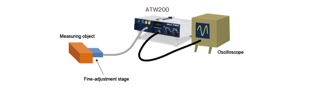
Hold the probe closer to the measuring object. It is recommended to attach fine-adjustment stage to enable slight movement.
Xin lưu ý rằng có thể có những khác biệt riêng về tông màu trên các thiết bị hiển thị như đèn LED, ống màn hình huỳnh quang và các màn hình LCD do quá trình sản xuất hoặc lô sản xuất khác nhau.
